
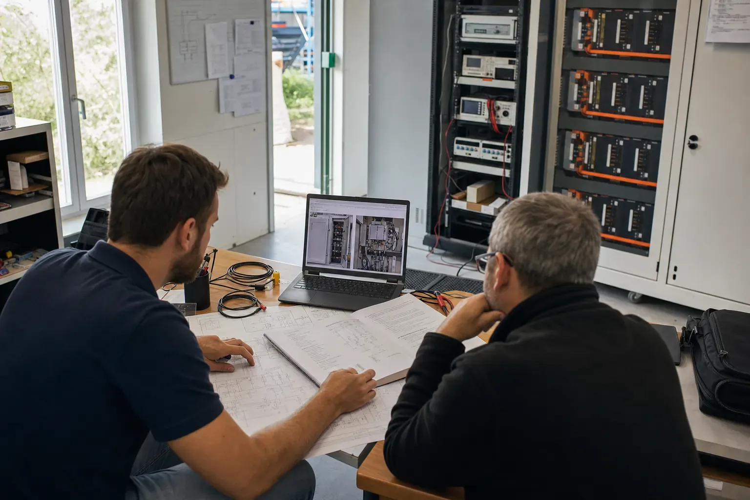
Use Energy Storage to Manage Cost, Capacity and Operational Risk.
MOLETONG helps commercial and industrial sites evaluate peak demand, time-of-use tariffs, solar utilization, transformer constraints and backup requirements before matching the right storage system.
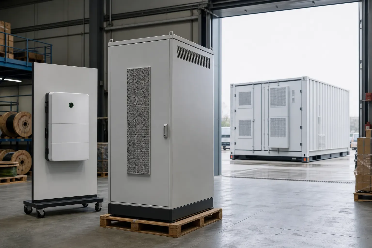
- Air-cooled and liquid-cooled options
- PV-ESS and on-grid architectures
- EMS monitoring and control
Illustrative site load profile
24-Hour Demand & Storage Response
Behind the meter
Built for the Pressures Behind the Meter.
High Peak-Period Cost
- Phenomenon
- Bills spike during peak tariff windows regardless of actual production demand.
- Impact
- Electricity cost becomes unpredictable and erodes operating margins.
- Possible Strategy
- Charge during off-peak periods; discharge to offset peak tariff consumption based on tariff and load profile.
Demand Spikes
- Phenomenon
- Short-duration load peaks trigger demand charges that persist for the billing month.
- Impact
- A single equipment start-up event can raise the monthly demand charge significantly.
- Possible Strategy
- Provide instantaneous power support to flatten peaks within the engineered power limit of the system.
Transformer Constraint
- Phenomenon
- Site load plus EV charging or new equipment approaches transformer rated capacity.
- Impact
- Expansion is blocked or requires costly grid upgrade with long lead time.
- Possible Strategy
- Coordinate storage charging power with site load so the combined draw remains within transformer capacity.
Unused Solar
- Phenomenon
- PV generation exceeds on-site consumption during midday, resulting in curtailment or low feed-in returns.
- Impact
- Capital invested in solar is underutilized; self-consumption ratio remains low.
- Possible Strategy
- Store available PV energy during generation surplus and dispatch it during evening or peak-tariff periods.
Outage Exposure
- Phenomenon
- Grid interruptions halt production lines or compromise cold-chain and critical processes.
- Impact
- Downtime cost and restart losses often exceed the cost of the outage itself.
- Possible Strategy
- Support defined critical loads with correct switching, PCS/STS configuration and system design -- scope requires engineering review.
Limited Visibility
- Phenomenon
- No real-time data on energy flows, battery state or fault conditions across the site.
- Impact
- Operational decisions are reactive; faults go undetected until they cause disruption.
- Possible Strategy
- Monitor system and fault status through EMS/HMS options; remote access and alerting subject to project configuration.
Economics
A Business Case Must Be Built From Your Data.
We do not recommend capacity from electricity spend alone. The business case depends on when power is used, how it is billed and what operational value the system must provide.
Data Required for a Meaningful Analysis
- 12-month electricity bills Consumption and demand charges by month
- 15 or 30-minute interval load data Actual demand curve, not just monthly totals
- Peak / off-peak tariff schedule Time-of-use rates and demand charge structure
- Transformer rated capacity And current peak utilization level
- PV system size and generation data If solar is already installed or planned
- Outage history and critical load list For backup sizing and STS configuration
- Operating shift schedule Production hours affect dispatch strategy
- Site single-line diagram Connection point, metering and protection layout
Calculation logic explorer
Illustrative -- not a quote
Indicative annual arbitrage value
¥ --
This figure reflects peak-valley tariff spread × daily usable energy × annual operating days only. It does not include demand charge reduction, solar self-consumption value, backup value, system cost, degradation, efficiency losses or financing. A complete business case requires your actual tariff schedule and interval load data.
Adjust the sliders to explore how tariff spread and capacity interact. Actual results depend on your site data and system configuration.
Operating strategies
One System Can Support Different Operating Strategies.
Actual strategy support depends on PCS, STS, EMS, metering, grid connection rules and project configuration. The following describes the operating logic, not a guaranteed outcome.
Peak-Valley Shifting
Charge the battery during low-tariff (valley) periods -- typically overnight or midday -- and discharge during high-tariff (peak) periods to reduce the cost of peak-rate consumption.
Note: Actual tariff windows vary by region and utility. Dispatch logic must be programmed into the EMS based on the specific tariff schedule.
Indicative operating timeline
Demand Management
Detect when site demand approaches a set threshold and discharge the battery to flatten the peak, reducing the recorded maximum demand used to calculate demand charges.
Note: Effectiveness depends on response speed of PCS, accuracy of demand prediction and available stored energy at the time of the event.
Indicative operating timeline
PV Self-Consumption
Store excess PV generation that would otherwise be curtailed or exported at low feed-in tariff rates. Discharge stored solar energy during evening hours or peak tariff periods.
Note: Requires PV-ESS architecture with DC-DC or AC coupling. Self-consumption ratio improvement depends on PV size, load profile alignment and battery capacity.
Indicative operating timeline
Transformer Capacity Protection
Monitor the combined draw of site load and ESS charging. When total demand approaches transformer rated capacity, reduce or pause charging to prevent transformer overload.
Note: This strategy does not replace transformer upgrades in all cases. Engineering review of transformer rating, protection coordination and load growth is required.
Indicative operating timeline
Load Following & Export Limitation
Adjust ESS output in real time to follow site load variations and prevent reverse power flow at the grid connection point, supporting export limitation requirements.
Note: Requires real-time metering at the grid connection point and EMS with sufficient control loop speed. Grid operator requirements vary.
Indicative operating timeline
Critical Load Backup
On grid failure, transfer defined critical loads to the ESS within the STS switching time. The system supports those loads until grid restoration or a predetermined duration.
Note: Backup capability requires appropriate PCS islanding function, STS, protection coordination and critical-load circuit separation. Backup duration depends on stored energy and critical load size.
Indicative operating timeline
System architecture
Typical C&I System Architecture.
The diagram below shows a representative on-grid C&I configuration. Actual architecture depends on site requirements, grid connection type and project scope.
Diagram is indicative. Actual architecture, protection and metering must be confirmed in project engineering.
Request Architecture DiscussionProduct platforms
C&I Platforms for Different Site Requirements.
Select a platform based on application requirements. Specifications below are from current brochure data and must be verified against the current datasheet before project use.
117 kWh Air-Cooled PV-ESS Cabinet
Applications
- Small to mid-size commercial sites
- PV self-consumption optimization
- Entry-level peak-valley shifting
Key Benefits
- Compact footprint for space-constrained sites
- Integrated PV-ESS architecture
- Suitable for single-cabinet deployment
- Capacity
- 117 kWh (brochure)
- Rated AC Power
- 60 kW
- Cooling
- Air-cooled
- Architecture
- PV-ESS
Specifications from current brochure. Must be verified against current datasheet before project use.
241 kWh Air-Cooled On-Grid Cabinet
Applications
- Medium commercial and light industrial
- On-grid peak shaving
- Demand charge management
Key Benefits
- Higher capacity for longer discharge duration
- On-grid architecture for straightforward integration
- Suitable for sites without existing PV
- Capacity
- 241 kWh (brochure)
- Rated AC Power
- 105 kW
- Cooling
- Air-cooled
- Architecture
- On-grid
Specifications from current brochure. Must be verified against current datasheet before project use.
261 kWh Liquid-Cooled PV-ESS Cabinet
Applications
- Industrial sites with high ambient temperature
- PV-ESS integration with optional DC-DC
- Sites requiring fast STS backup configuration
Key Benefits
- Liquid cooling for high-cycle and hot-climate environments
- Optional PV DC-DC connection
- Fast STS configuration available
- Capacity
- 261 kWh (brochure)
- Rated AC Power
- 125 kW
- Cooling
- Liquid-cooled
- Architecture
- PV-ESS + optional DC-DC
- STS
- Fast STS option available
Specifications from current brochure. Must be verified against current datasheet before project use.
261 kWh Liquid-Cooled On-Grid Cabinet
Applications
- Industrial and commercial on-grid storage
- High-temperature or high-cycle environments
- Compact liquid-cooled configuration
Key Benefits
- Liquid cooling in a compact form factor
- Suitable for demanding ambient conditions
- On-grid integration
- Capacity
- 261 kWh (brochure)
- Rated AC Power
- 125 kW
- Cooling
- Liquid-cooled (compact)
- Architecture
- On-grid
Specifications from current brochure. Must be verified against current datasheet before project use.
261 kWh Semi-Solid Configuration
Applications
- Multi-function integrated configuration
- Sites requiring PV, on-grid and off-grid capability
- Application and certification require confirmation
Key Benefits
- Integrated multi-mode functions per brochure
- Flexible architecture options
- Capacity
- 261 kWh (brochure)
- Architecture
- PV / On-grid / Off-grid
- Cell type
- Semi-solid (per brochure)
- Note
- Application and certification require confirmation
Specifications from current brochure. Must be verified against current datasheet before project use.
418 kWh Liquid-Cooled Cabinet
Applications
- Large commercial and industrial sites
- High-capacity peak shaving and arbitrage
- Multi-cabinet parallel configurations
Key Benefits
- Highest single-cabinet capacity in the C&I range
- Multiple AC power and grid voltage options
- Suitable for large-scale C&I and EPC projects
- Capacity
- 418 kWh (brochure)
- AC Power
- Multiple options per brochure
- Grid Voltage
- Multiple options per brochure
- Cooling
- Liquid-cooled
Specifications from current brochure. Must be verified against current datasheet before project use.
Why MOLETONG
The Cabinet Is Only One Part of a Working Project.
Our project approach connects equipment selection with transformer, metering, protection, communications and operating strategy. We work with you from site data through to commissioning and monitoring.
- Founded
- 2011
- Dongguan, Guangdong
- Production Base
- 01
- Dongguan manufacturing
- Sales Centers
- 04
- Domestic network
- Overseas Office
- Indonesia
- Local company established
Engineering Center
Dongguan engineering center supporting system design, sizing simulation and technical documentation for C&I and utility-scale projects.
Electrical & PV Experience
Application experience connecting storage systems with distribution, solar, load and project site requirements across different configurations.
System Matching & Commissioning
Equipment selection matched to site requirements, followed by commissioning support and EMS/HMS monitoring configuration.
Indonesia Local Presence
Overseas office and local company in Indonesia supporting regional projects, Energy-as-a-Service pathway and local customer relationships.
Safety & specifications
Safety Architecture and Key Specifications.
The following specifications apply only to the listed product configurations and must be verified against the current datasheet before project use.
LFP Chemistry
- LiFePO₄ 314 Ah cells
- Inherently stable cathode chemistry
- Lower thermal runaway risk vs NMC
- No cobalt in cathode
8,000 Cycle Brochure Condition
- 0.5P charge/discharge rate
- 5%-95% depth of discharge
- 70% state of health threshold
- Brochure condition -- verify in datasheet
IP54 + Cooling Options
- IP54 ingress protection standard
- C3 corrosion class standard
- Higher corrosion class optional
- Air-cooled and liquid-cooled variants
Fire Protection Options
- Fire detection system
- Suppression options per configuration
- Thermal management integration
- Configuration-specific -- confirm in project
Certificates & Technical Documents
Documents available according to project stage and product configuration. Contact engineering to request specific certificates or test reports.
All specifications listed are from current brochure data. Cycle life, IP rating, corrosion class and fire protection availability vary by product configuration and must be confirmed in the current datasheet and project engineering documentation.
Application evidence
Application Frameworks and Authorized References.
The default examples below are representative design frameworks. When authorized project records are available, we can share relevant references during due diligence.
 Manufacturing
Industrial Manufacturer -- Peak Demand & Cost Management
- Challenge
- High peak-period electricity costs and recurring demand charges were eroding margins. Transformer capacity was approaching limits during shift changes.
- System
- Air-cooled on-grid ESS cabinet with EMS integration and demand threshold control.
- Scope
- Single-cabinet deployment at distribution board level; EMS connected to site SCADA.
- Result
- Peak demand profile flattened within engineered power limit. Actual financial outcome subject to site-specific tariff and operating data -- indicative only.
Industrial Park
Industrial Park -- Transformer Capacity & Tenant Load Growth
- Challenge
- New tenant equipment and EV charging demand pushed combined load toward transformer rated capacity, blocking further expansion.
- System
- Liquid-cooled ESS with transformer coordination logic in EMS; charging power managed in real time against transformer headroom.
- Scope
- Multi-tenant metering integration; EMS configured for transformer protection and tenant-level monitoring.
- Result
- Transformer utilization managed within rated capacity during peak periods. Expansion proceeded without immediate grid upgrade. Outcome subject to engineering confirmation.
PV-ESS Integration
Commercial Facility -- Solar Self-Consumption Improvement
- Challenge
- Midday PV surplus was being exported at low feed-in rates. Evening peak tariff consumption remained high.
- System
- PV-ESS cabinet with DC-DC coupling; dispatch strategy optimized for self-consumption and evening peak discharge.
- Scope
- Integrated with existing rooftop PV system; EMS configured for self-consumption priority with peak-valley shifting.
- Result
- Self-consumption ratio improved. Evening peak tariff consumption reduced. Actual improvement depends on PV size, load profile and tariff structure.
Assessment process
From Data to Operational System.
-
01
Data Submission
Upload electricity bills, interval load data, tariff schedule and site single-line diagram.
-
02
Site Review
Engineering team reviews load profile, tariff structure, transformer capacity and site constraints.
-
03
Simulation & Sizing
Model storage dispatch against actual load data to size capacity and power for the target operating strategy.
-
04
Proposal
Present system configuration, architecture, indicative economics and project scope.
-
05
Engineering & Implementation
Detail design, procurement, installation and protection coordination.
-
06
Commissioning
System testing, EMS configuration, dispatch strategy verification and handover.
-
07
O&M
Ongoing monitoring via EMS/HMS, performance review and maintenance support.
Frequently asked
Common Questions.
How much can we save?
Savings depend entirely on your tariff structure, load profile and how the system is sized and operated. We do not publish a standard saving percentage because the business case must be built from your actual electricity data. Submit your bills and interval load data for a site-specific analysis.
Will storage solve a transformer capacity limit?
Storage can support certain transformer constraints when correctly engineered -- specifically by coordinating charging power with site load so the combined draw stays within transformer rated capacity. It does not replace every grid upgrade. Whether it is the right solution depends on the nature of the constraint, load growth projections and site configuration.
Can the system provide backup power?
Backup capability requires appropriate PCS islanding function, a static transfer switch (STS), protection coordination and a defined critical-load circuit. It is not a standard feature of all configurations. Backup duration depends on stored energy and the size of the critical load. This requires engineering design -- not just a cabinet selection.
Can multiple cabinets be used in parallel?
Multiple cabinet configurations are possible subject to system parallel capability, site electrical design and EMS coordination. This is a project engineering question -- contact us with your capacity and power requirements and we will assess the configuration options.
What documents are available?
Datasheets, interface drawings, installation documentation, test reports and certificates are available according to project stage and product configuration. Contact engineering to request specific documents for a project under evaluation.
How long does the assessment process take?
An initial review of your electricity data and load profile typically takes one to two weeks. Full simulation, sizing and proposal timelines depend on the complexity of the site and the completeness of the data submitted.
Do you support projects outside China?
Yes. We have an office and local company in Indonesia and work with EPC and energy service companies on international projects. Grid connection requirements, certification and local regulations must be confirmed for each project location.
Start the assessment
Start With Your Electricity Data.
Upload recent bills, interval data or a single-line diagram. We will review whether storage fits the site before recommending a system.
- No system recommendation before reviewing your data
- Engineering review of tariff, load and site constraints
- Site-specific analysis -- no generic saving estimates
- Data handled confidentially -- see privacy note below
Privacy
Documents and data submitted through this form are used solely for the purpose of conducting a technical and commercial assessment of your site. Files are not shared with third parties without your consent. You may request deletion of submitted data at any time by contacting us directly.