
Multi-MWh Liquid-Cooled Platforms for Larger Energy Projects.
Select DC-side or integrated AC/DC container architectures according to project power, duration, grid, PCS and balance-of-plant requirements.
- Chemistry
- LFP
- Cooling
- Liquid
- Platform Range
- 2.5-5MWh
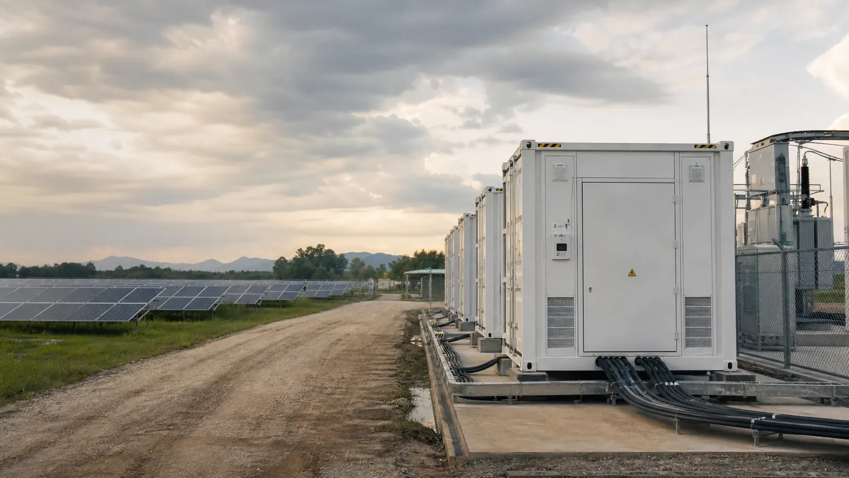
Multi-container array · DC and AC/DC integrated platforms
Factory Acceptance Testing and field deployment documentation available on request.
Step 1 · Responsibility Boundary
DC-Side or AC/DC Integrated?
The architecture choice determines the scope boundary between the container supplier and the EPC. Confirm this before comparing capacity or pricing.
Battery block. You select the PCS.
The container delivers a standardised high-voltage DC battery block. The EPC or integrator is responsible for selecting, procuring and connecting the PCS, MV transformer and grid protection.
Included in container scope
- LFP battery clusters with BMS
- Intelligent liquid cooling system
- DC combiner and internal protection
- Environmental monitoring (temp / humidity / CO / H₂)
- Communication interface to EMS/SCADA
EPC / integrator responsibility
- PCS selection, procurement and commissioning
- MV transformer and switchgear
- Grid protection relay coordination
- EMS/SCADA integration
Representative platform
5.016 MWh DC-Side Container
Battery and PCS in one enclosure.
The container includes the battery, PCS and associated controls within a single packaged unit. The EPC connects at the AC output terminal, reducing interface coordination scope.
Included in container scope
- LFP battery clusters with BMS and liquid cooling
- Air-cooled PCS integrated within the container
- Internal DC combiner and protection
- Environmental monitoring and fire detection
- AC output terminals ready for MV transformer connection
EPC / integrator responsibility
- MV transformer and switchgear
- Grid protection relay coordination
- EMS/SCADA integration to site level
Representative platforms
2.5 MWh / 3.34 MWh · 4.17 MWh
Architecture selection note. We use this framework to start the conversation, then agree a project-specific scope matrix with your EPC or integration team before contract so every interface and responsibility is clear.
Platform 01 · DC-Side
5.016 MWh DC-Side Container
A high-capacity standardised battery block designed for renewable integration and grid-scale projects where the EPC selects and supplies the PCS and MV architecture. The container delivers a defined DC output voltage window and communication interface.
Specification Reference · Verify against current datasheet
- Usable Energy
- 5.016 MWh
- Nominal Voltage
- 1331.2 V DC
- Operating Voltage Window
- 1164.8 - 1497.6 V DC
- Cell Capacity
- 314 Ah LFP
- Cooling
- Intelligent liquid cooling
- Power Configuration
- 2.5 MW at 0.5P · 5 MW at 1P
- Enclosure Rating
- IP55
- Approximate Weight
- ~42 t (auxiliary variation applies)
Items requiring current datasheet confirmation
- -- Fire suppression system type, agent and activation logic
- -- Physical container format (20-foot or other) and exact external dimensions
- -- Auxiliary power consumption and supply requirements
Monitoring
Temperature · Humidity · CO · H₂ · Water ingress
Communication
BMS to EMS interface -- protocol to be confirmed per project
Specification Reference · Verify against current datasheet
Variant A
1250 kW / 2.5 MWh
- Rated Power
- 1250 kW
- Energy
- 2.5 MWh
Variant B
1670 kW / 3.34 MWh
- Rated Power
- 1670 kW
- Energy
- 3.34 MWh
- Grid Voltage Options
- 400 V / 690 V / 800 V
- Battery Cooling
- Liquid cooling
- PCS Cooling
- Air cooling
- Cell Chemistry
- LFP
Interface reduction benefit
By integrating the battery and power-conversion functions within a single packaged solution, the EPC connects at the AC output terminal. This reduces the number of cross-supplier interface documents required during project engineering.
Platform 02 · AC/DC Integrated
2.5 MWh / 3.34 MWh Integrated AC/DC Container
Reduce interface coordination by integrating battery and power-conversion functions within a packaged solution. Two capacity variants share the same platform architecture.
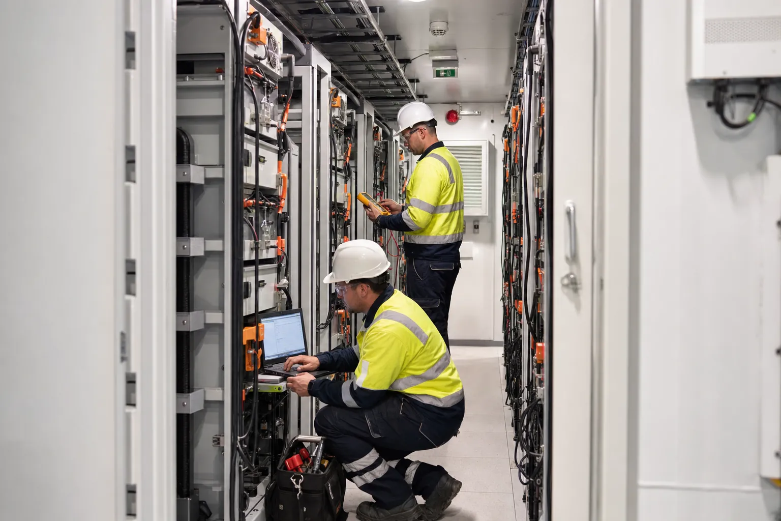
Battery section
Liquid-cooled LFP clusters with BMS
PCS section
Air-cooled inverter with AC output terminals
Platform 03 · AC/DC Integrated · 2 MW Class
4.17 MWh Integrated AC/DC Container
A 2 MW-class integrated configuration for larger project blocks. The platform combines a high-voltage LFP battery with an integrated PCS within a single container.
Specification Reference · Verify against current datasheet
- Usable Energy
- 4.17 MWh
- Rated Power
- 1670 kW
- Maximum Power (per table)
- 2000 kW
- Battery Nominal Voltage
- 1331.2 V DC
- Cell Capacity
- 314 Ah LFP
- Cooling
- Liquid cooling
- Enclosure Rating
- IP54
Physical format confirmation required
Ask us for the current general-arrangement drawing and datasheet before using dimensions in project documents. We will confirm the physical format, external dimensions and internal layout for the selected platform.
Architecture
AC/DC Integrated
Class
~2 MW
Chemistry
LFP
Step 2 · Project Interface
Battery to Grid: Interface Responsibilities
Each interface point below carries a defined responsibility. Confirm the responsible party for each item in the project scope matrix before detailed engineering begins.
| Interface / Scope Item | DC-Side Container | AC/DC Integrated | Notes |
|---|---|---|---|
| Battery clusters and BMS | MOLETONG | MOLETONG | Included in container scope for both architectures |
| DC combiner and internal protection | MOLETONG | MOLETONG | Confirm fuse / breaker ratings per project |
| PCS (power conversion system) | EPC / integrator | MOLETONG | DC-side: EPC selects and supplies PCS |
| MV transformer | EPC / integrator | EPC / integrator | Confirm ratio, impedance and protection grading |
| MV switchgear | EPC / integrator | EPC / integrator | Protection relay coordination required |
| Auxiliary power supply | EPC / integrator | EPC / integrator | Confirm voltage, phase and capacity per container |
| EMS / SCADA integration | EPC / integrator | EPC / integrator | MOLETONG provides BMS communication interface; protocol to be confirmed |
| Fire suppression system | MOLETONG (internal) | MOLETONG (internal) | External site fire system by EPC; confirm local code requirements |
| Environmental monitoring | MOLETONG | MOLETONG | Temp / humidity / CO / H₂ / water ingress |
| Communication wiring and cable route | EPC / integrator | EPC / integrator | Confirm cable entry point and conduit requirements |
| Civil works, foundations and drainage | EPC / integrator | EPC / integrator | MOLETONG provides GA drawing and load data |
We turn this indicative matrix into an agreed, project-specific scope document before contract, so your team knows exactly who owns each responsibility.
Step 3 · Safety and Environment
Protection, Monitoring and Operating Conditions
The containers include layered protection functions and environmental monitoring. Operating limits must be verified against the current datasheet and confirmed within the project design.
Environmental Monitoring
- -- Temperature sensing across battery clusters
- -- Humidity detection inside enclosure
- -- Carbon monoxide (CO) detection
- -- Hydrogen gas (H₂) detection
- -- Water immersion / ingress detection
- -- Smoke and thermal detection (fire system)
Protection Functions
- -- Short circuit protection
- -- Lightning and surge protection
- -- Overcharge and overdischarge protection
- -- Over-temperature shutdown
- -- Fire detection and suppression activation
- -- Emergency stop (e-stop) function
- -- Uninterruptible power supply (UPS) for control systems
Operating Conditions
- -- Operating temperature range -- confirm per datasheet; derating may apply
- -- Storage temperature range -- confirm per datasheet
- -- Altitude -- confirm maximum altitude and derating schedule
- -- Humidity -- confirm non-condensing limits
- -- Corrosion class -- confirm C-class for coastal or industrial sites
- -- Local fire code -- confirm compliance requirements with the AHJ
Operating limits are project-specific. The protection functions and monitoring capabilities listed above are general descriptions based on platform brochure data. Actual operating limits, derating curves and fire suppression details must be confirmed against the current version of the product datasheet and within the project engineering design. Do not operate the system outside verified limits.
Step 4 · Logistics and Site
Delivery, Installation and Commissioning
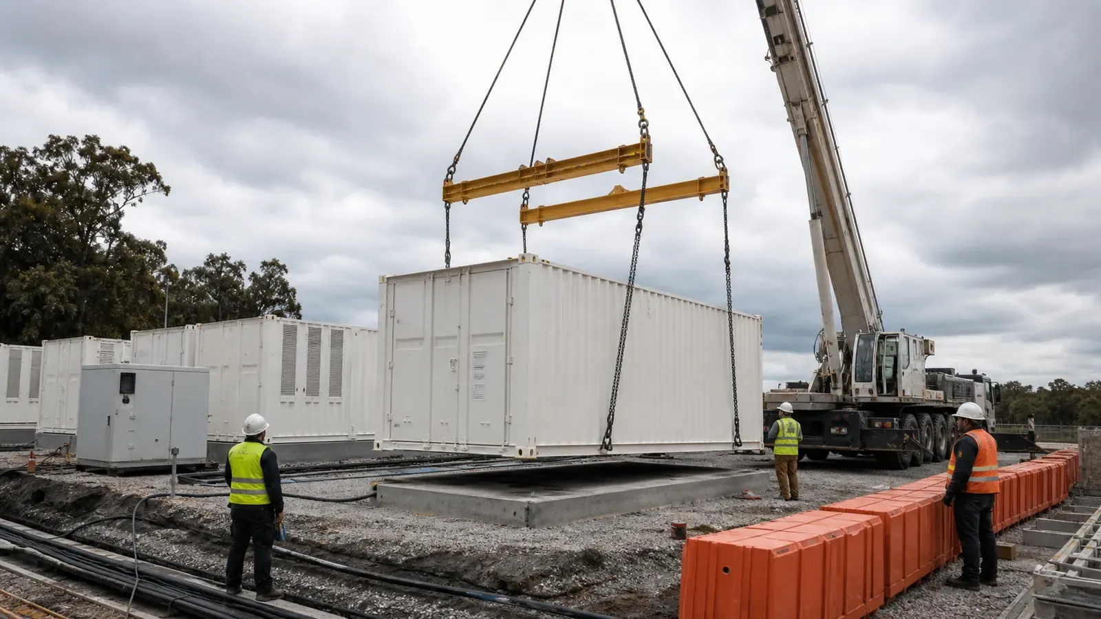
Plan lifting weight, access routes, foundation, container spacing, drainage, cable routing, crane plan and commissioning sequence before container delivery.
01 · Lifting
Crane Plan and Lifting Weight
Confirm gross lifting weight per container including auxiliaries. Prepare crane plan, spreader bar requirements and lift point verification before delivery.
02 · Foundation
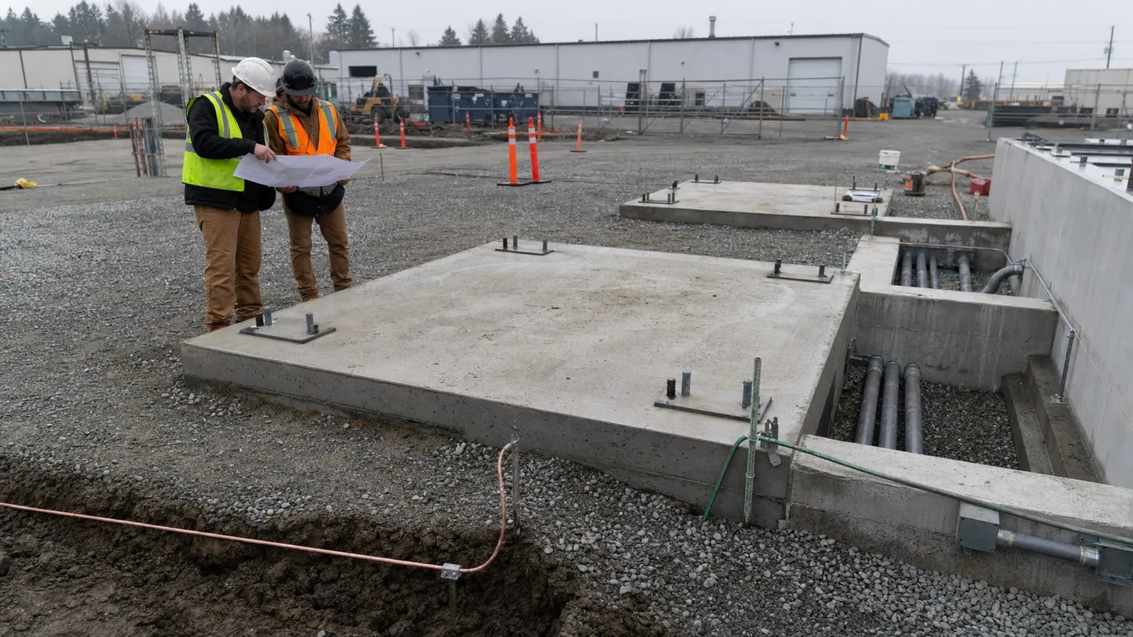
Foundation, Spacing and Drainage
Foundation design must accommodate container load and levelling requirements. Minimum container spacing and drainage channel routing are defined in the GA drawing.
03 · Cable and Access
Cable Route and Entry Points
Confirm cable entry locations, conduit sizing, DC cable routing to PCS and communication cable segregation requirements from the interface list.
04 · Commissioning
FAT, SAT and Commissioning Sequence
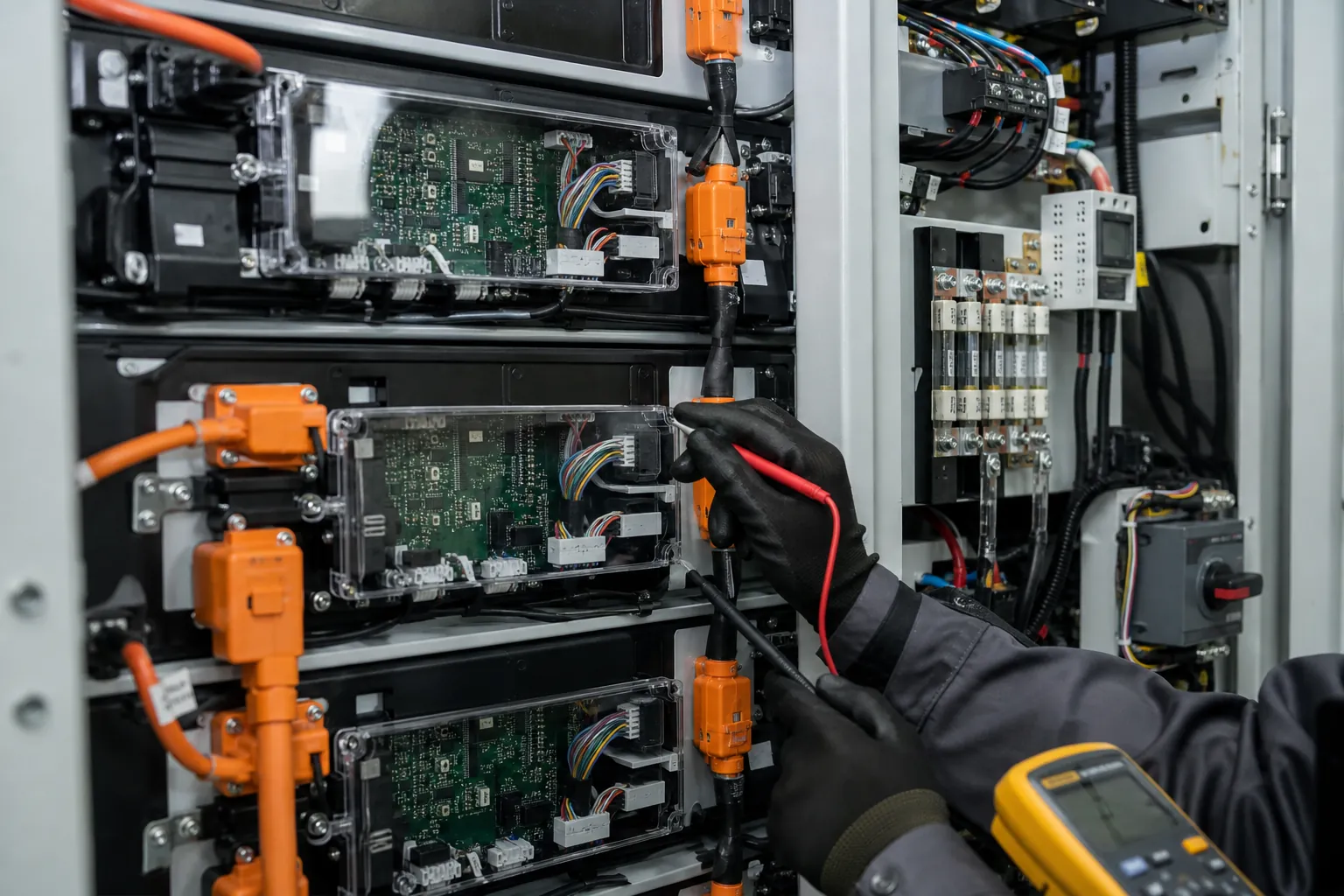
Factory Acceptance Testing is conducted before shipment. Site Acceptance Testing and commissioning sequence are agreed in the project documentation package.
Site Preparation Checklist
Confirm gross lifting weight and arrange crane with adequate rated capacity
Prepare access road with sufficient width and load-bearing capacity for transport vehicle
Complete foundation to GA drawing requirements before container delivery
Verify container spacing meets minimum clearance for maintenance and fire access
Install drainage channels and confirm water management before energisation
Confirm auxiliary power supply is available before commissioning begins
Step 5 · Documentation
Project Documentation and Verification
Confirm which documents are required for your project, jurisdiction and lender. Request the full documentation package at the time of enquiry.
Engineering Drawings
- -- General arrangement (GA) drawing
- -- Interface list and terminal schedule
- -- Single-line diagram (SLD)
- -- Cable entry and conduit drawing
Technical Documents
- -- Product datasheet (current version)
- -- BMS communication protocol document
- -- EMS/SCADA integration guide
- -- Auxiliary power and load schedule
Testing and Acceptance
- -- Factory Acceptance Test (FAT) plan and report
- -- Site Acceptance Test (SAT) plan and checklist
- -- Commissioning procedure and sequence
- -- Test certificates and calibration records
Certification and Compliance
- -- Product certifications (confirm applicable standards)
- -- Fire system documentation and approval
- -- Local authority / AHJ submission documents
- -- Material safety data sheets (MSDS)
Warranty and O&M
- -- Warranty terms and conditions document
- -- Operation and maintenance (O&M) manual
- -- Spare parts list and lead time schedule
- -- Fault code reference and troubleshooting guide
Request the Full Package
Send your Basis of Design and single-line diagram to receive the project-relevant documentation set. Indicate which documents are required for lender, grid authority or local permitting.
Send Basis of DesignFrequently Asked Questions
Questions from EPC and Integration Teams
DC-side or AC/DC integrated -- how do I choose?
The decision is primarily about EPC responsibility and interface scope. If the EPC has an existing PCS vendor relationship, is integrating with a specific grid-tied inverter, or requires a particular DC voltage window, the DC-side container gives the EPC control over the PCS selection. If the project benefits from reduced interface coordination and the EPC is connecting at the AC terminal, the AC/DC integrated container reduces the number of cross-supplier interface documents required during engineering. Confirm the responsibility boundary in the project scope matrix before contract.
Can the DC-side container be used with our existing PCS?
Compatibility requires a technical review. The PCS must be rated for the battery operating voltage window (1164.8 - 1497.6 V DC for the 5.016 MWh platform), the maximum charge and discharge current, and the communication protocol used by the BMS. Grid protection coordination between the BMS, PCS and grid relay must also be reviewed. Do not assume compatibility without completing a formal interface review between the BMS vendor and the PCS vendor.
What is included in the container scope of supply?
The general scope description on this page is a starting point only. The exact scope of supply -- including fire suppression, UPS, environmental monitoring, communication hardware, auxiliary power and any pre-wired items -- must be confirmed in the project-specific scope matrix agreed between MOLETONG and the EPC before contract. Do not rely on the general descriptions on this page to define the scope for a live project.
Can the containers operate in extreme environments?
The containers are designed for outdoor installation with IP55 or IP54 enclosure ratings and intelligent liquid cooling. However, operation is only permissible within the verified temperature, altitude, humidity and corrosion limits defined in the current product datasheet. High-altitude sites, coastal environments, extreme temperature ranges and sites with local fire code requirements may require derating, additional protection measures or design modifications. Confirm the project site conditions with MOLETONG engineering before finalising the design.
What communication protocol does the BMS use?
The BMS provides a communication interface to the EMS/SCADA system and, for the DC-side platform, to the PCS. The specific protocol, register map and physical interface must be confirmed in the communication protocol document provided as part of the project documentation package. Request this document at the time of enquiry and share it with your PCS vendor and EMS integrator for compatibility review.
What is the lead time and delivery process?
Lead time depends on project volume, configuration and current production schedule. Factory Acceptance Testing is conducted at the Dongguan production base before shipment. Shipping, port clearance and site delivery logistics must be planned in coordination with the project schedule. Contact MOLETONG engineering with your project timeline to receive a lead time estimate specific to your order.
Project Engineering Enquiry
Define the Interfaces Before Finalizing the Container.
Send your Basis of Design and single-line diagram. The MOLETONG engineering team will review the architecture selection, interface responsibilities, operating conditions and documentation requirements for your project.
Enquiries are reviewed by the MOLETONG engineering team. Response time depends on project complexity and current enquiry volume.
What to include
Basis of Design checklist
-
01
Project overview
Location, capacity (MWh and MW), grid voltage, project type (solar+storage, standalone, microgrid).
-
02
Architecture preference
DC-side or AC/DC integrated; PCS vendor if already selected; EMS/SCADA platform.
-
03
Single-line diagram
Preliminary or conceptual SLD showing the battery, PCS, MV transformer and grid connection point.
-
04
Site and schedule
Site conditions (altitude, temperature range, corrosion class), target delivery date and commissioning window.
All information shared is treated as confidential and used only for the purpose of responding to your project enquiry.