
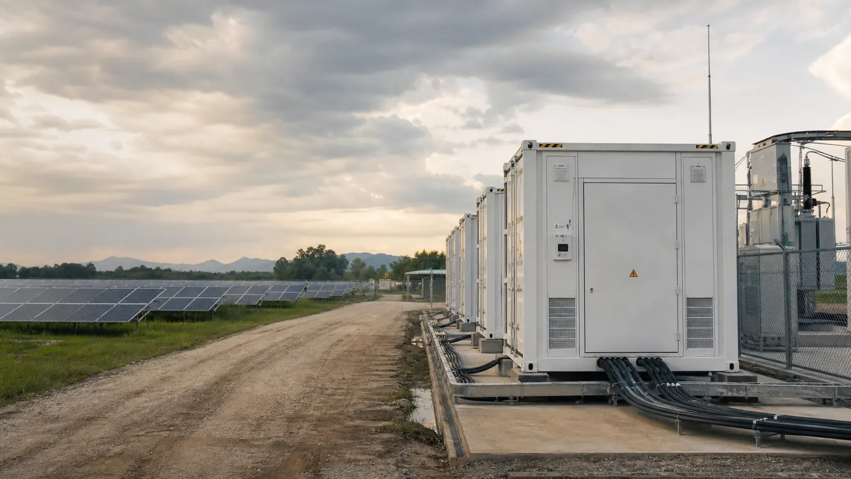
Scalable Storage for Renewable,
Grid and Microgrid Projects.
Combine containerized LFP storage, PCS, electrical infrastructure and energy management around the project's power, duration, grid and operating requirements.
Where these systems are deployed.
From large-scale renewable co-location to remote island microgrids, the platform is configured around the project's grid context, dispatch strategy and site constraints.
Renewable Co-location
Battery storage co-located with utility-scale PV or wind to smooth generation, extend dispatch windows and meet grid interconnection requirements.
Peak Regulation & Load Shifting
Grid-connected storage for demand peak shaving, tariff arbitrage and ancillary service provision where grid codes permit.
Microgrid & Industrial Park
Behind-the-meter or islanded microgrid configurations for industrial parks, campuses and special economic zones requiring reliable, managed power.
Remote & Island Power Systems
Diesel displacement and renewable-storage hybrid systems for islands and off-grid communities where grid connection is unavailable or uneconomical.
Grid Support Services
Frequency response, voltage support and spinning reserve where local grid codes and offtake agreements define the operating envelope.
Multi-Container Expansion
Block architecture allowing phased capacity additions. Each expansion phase requires interface review, site approvals and engineering sign-off.
Utility projects fail at interfaces, not only at product selection.
The matrix below maps the critical interface zones where scope gaps and assumption mismatches most often cause schedule and cost overruns. Each zone requires explicit agreement before engineering begins.
| Interface Zone | Risk if Unresolved | Scope Owner |
|---|---|---|
| DC voltage & current range | PCS underspecification, cell stress | MOLETONG + PCS vendor |
| AC bus & PCS topology | Protection coordination failure | Project EPC |
| MV transformer & switchgear | Harmonics, insulation mismatch | Project EPC / utility |
| Grid code compliance | Interconnection rejection | Developer + local utility |
| Fire suppression & spacing | Code non-compliance, permit delay | Site EPC + AHJ |
| Foundation & civil loading | Structural failure, warranty void | Civil contractor |
| SCADA / EMS communication | Dispatch failure, data loss | MOLETONG + system integrator |
| Commissioning responsibility | SAT failure, liability gap | Defined in contract |
Note: Scope ownership above reflects typical project structures and does not constitute a contractual commitment. Each project requires an explicit interface agreement and scope-of-supply document before engineering commences.
DC-side and AC/DC integrated configurations.
The diagram shows the typical supply boundary for MOLETONG-scope equipment. Balance of plant -- including transformers, MV switchgear, civil works and grid connection -- is project-specific and requires coordination with the EPC and local utility.
Three containerized platforms.
Platform selection depends on project power, duration, grid topology and site constraints. All parameters below are drawn from current brochure data and must be verified against the applicable model datasheet and project technical agreement before engineering use.
5.016 MWh DC-Side Liquid-Cooled Container
Large-format DC-side platform for utility and grid-scale projects. PCS and MV scope are project-specific and must be engineered separately.
- Capacity
- 5.016 MWh
- Cell chemistry
- LFP 314Ah
- Rated voltage
- 1331.2 V DC
- Configuration
- 0.5P / 1P
- Format
- 20-foot ISO
- Protection
- IP55
Integrated AC/DC Container -- 2.5 MWh / 3.34 MWh
20-foot integrated platform combining battery, PCS and AC connection in a single container. Simplifies site installation and reduces BOP scope.
- AC variants
- 1250 kW / 1670 kW
- Format
- 20-foot integrated
- Topology
- AC/DC integrated
- Cell chemistry
- LFP
- Cooling
- Liquid-cooled
- Application
- C&I / Utility
Integrated AC/DC Container -- 4.17 MWh
2 MW-class integrated configuration. Container size information must be verified; current brochure references a 40-foot dimension which requires confirmation against the applicable datasheet.
- Capacity
- 4.17 MWh
- Power class
- 2 MW-class
- Topology
- AC/DC integrated
- Cell chemistry
- LFP
- Cooling
- Liquid-cooled
- Container
- Verify dimensions
All parameters must be verified. Product specifications evolve with model revisions. The values above are drawn from brochure data at time of publication. Always confirm against the latest model datasheet and project technical agreement before use in engineering, procurement or investment decisions.
Manage temperature, detection and protection as one system.
Effective safety in containerized storage is a layered engineering problem, not a single feature. The following describes the system approach; specific capabilities vary by platform and must be confirmed against the applicable model documentation.
Thermal Management
- Liquid cooling system
- Cell-level temperature monitoring
- Thermal runaway containment design
- Ambient temperature management
Environmental Detection
- Temperature & humidity sensors
- CO and H₂ gas detection
- Water immersion detection
- Smoke detection
Fire Suppression
- Fire suppression system options
- Automatic activation on detection
- Manual override capability
- Integration with site alarm systems
Protection & Emergency Stop
- Emergency stop (E-stop) function
- UPS for control systems
- Lightning protection
- Short-circuit protection
Safety capability note: The layers above describe the system design approach. Specific sensor types, suppression agents, detection thresholds and protection coordination depend on the platform model and project configuration. No absolute safety guarantee is expressed or implied. All safety systems must be reviewed against applicable local codes and site-specific requirements.
What we need to scope your project accurately.
Share the following inputs and we can make the first technical discussion specific to your project instead of offering a generic response.
MW / MWh and duration target
Power, energy and discharge duration requirements
Grid voltage, frequency and code
Point of connection voltage, Hz, applicable grid standard
PCS topology preference
Central, string, or project-specified PCS arrangement
Ambient, corrosion and altitude
Site environmental classification and elevation
Site layout and fire spacing
Container arrangement, setbacks and access requirements
Dispatch strategy
Arbitrage, frequency response, peak shaving or hybrid
Target COD
Commercial operation date and key project milestones
FAT / SAT and documentation
Factory acceptance, site acceptance and certification needs
Document uploads
Accepted project documents
- Single-line diagram (SLD)
- Technical specification or scope of work
- Grid connection agreement or utility requirements
- Site layout or plot plan
- Environmental and geotechnical data
- Existing SCADA / EMS interface specification
From basis of design to operational system.
Each phase requires defined inputs and agreed outputs before the next begins. Schedule durations depend on project scope, site readiness and interface complexity.
-
01
Basis of Design
MW/MWh, grid, site, dispatch and compliance inputs agreed
-
02
Interface Review
DC, AC, MV, comms, fire and civil scope boundaries confirmed
-
03
Product & Configuration
Platform selection, BOM and technical specification issued
-
04
Project Engineering
Detailed design, drawings, protection coordination
-
05
FAT & Logistics
Factory acceptance test, packing, shipping and customs
-
06
Installation Coordination
Civil, mechanical and electrical installation support
-
07
SAT & Commissioning
Site acceptance test, grid energisation and handover
-
08
O&M
Ongoing monitoring, remote diagnostics and service support
All interface zones must be agreed in writing before engineering commences. Undefined interfaces are the primary cause of project delays.
Factory acceptance test protocols, ITP and quality records are prepared per project requirements and agreed certification standards.
Delivery schedule is driven by site readiness, permit status, grid connection milestones and logistics routing. Discuss your COD target early.
Verified MOLETONG project references.
Only projects confirmed as MOLETONG scope and approved for public disclosure are listed. Attribution is not published without verification. Contact us to discuss specific project references under NDA if required.
Guangdong, China
- Scale
- Verify with MOLETONG
- Product
- Commercial / Industrial BESS
- MOLETONG scope
- Storage supply and commissioning support
- Evidence
- Reference available on request
Indonesia
- Scale
- Verify with MOLETONG
- Product
- Energy as a Service deployment
- MOLETONG scope
- EaaS structure, storage and EMS
- Evidence
- Reference available on request
Domestic projects · China
- Scale
- Multiple scales
- Product
- Residential and C&I storage
- MOLETONG scope
- Product supply via sales network
- Evidence
- Reference available on request
Attribution policy: Project references are only published with verified MOLETONG scope attribution and explicit approval for public disclosure. Unverified project claims are not published. For detailed project references, operating data or site visits, contact our engineering team. NDA arrangements are available for qualified project discussions.
Technical questions answered.
Questions that arise most often in early-stage project conversations. For project-specific technical discussion, use the form below.
Is the 5.016 MWh product AC or DC side?
The current brochure presents the 5.016 MWh platform as a DC-side container. PCS, MV transformer, switchgear and grid connection scope are project-specific and must be engineered and procured separately. The scope boundary should be agreed explicitly before project engineering commences.
Can you provide integrated AC/DC container options?
Yes. The current brochure includes 2.5 MWh / 3.34 MWh (1250 kW and 1670 kW AC variants) and a 4.17 MWh (2 MW-class) integrated AC/DC platform. Exact current model designations, full specifications and container dimensions must be confirmed against the applicable datasheet before engineering use.
Can containers be combined for larger projects?
Yes, in a properly engineered block architecture. Multi-container configurations require explicit interface engineering, protection coordination, site layout approval and, where applicable, utility or regulatory approval. Each expansion phase is treated as an engineering project in its own right.
What project documents are required to begin a technical assessment?
At minimum: basis of design covering MW/MWh and duration, grid voltage, frequency and applicable code, site layout, environmental classification and target COD. Useful additions include a single-line diagram, grid connection agreement, existing SCADA/EMS interface specification and technical scope of work.
What grid codes and certifications do the products support?
Applicable certifications and grid code compliance depend on the specific model and target market. This must be confirmed against the current product documentation and project requirements. Contact our engineering team with your grid code reference and we will advise on the applicable model and certification status.
How is the EMS/SCADA integration handled?
MOLETONG provides HMS and EMS capability within the supply boundary. Integration with project SCADA, utility metering and third-party control systems is a project-specific scope item requiring an interface specification. This should be identified and agreed during the interface review phase.
What is the warranty and O&M support structure?
Warranty terms, O&M support scope and remote monitoring arrangements are defined in the project contract. These vary by project type, geography and agreed service level. Discuss your O&M requirements as part of the technical discussion.
Share your project basis of design.
A technical discussion starts with your project data. Provide as much detail as possible -- power, duration, grid context, site constraints and target COD -- so we can give you a substantive response rather than a generic one.
Request a Technical Discussion
Fill in your project details and we will respond within 2 business days.