

What to Verify About Heat Rise in Low-Voltage Panels
Heat rise in low-voltage panels is a serious risk. Judging it from a single catalog number often leads to failures. The real answer lies in your project's specific operational data.
To properly verify heat rise, you must ensure the low-voltage panel's selection traces directly back to your project’s study values and operating scenarios. This involves checking the load profile, fault levels, protection settings, and internal arc requirements against the panel’s verified design and test reports.
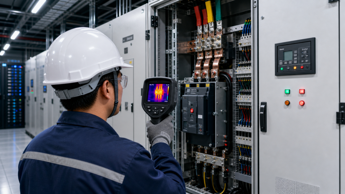 " alt="Engineer conducting a thermal inspection of low-voltage switchgear" title="Verifying Low-Voltage Panel Heat Rise with Data." decoding="async" loading="lazy" />
Heat-rise decisions are easily distorted by a single catalogue rating. Our rule is to connect the proposed hardware back to the load-flow, fault and protection studies, the enclosure arrangement and the real installation environment.
This article will walk you through that exact process. We will look at how load, fault levels, and protection needs change the cost, performance, and risk profile of your equipment. Our goal is to show you the reasoning transparently, so you can see when a solution applies to your project—and when it does not.
Treat Heat Rise as a Measurable Design Decision
Thinking of heat rise as a simple pass/fail number is a mistake. This ignores how critical design choices directly impact your cost, safety, and performance. You must reframe it as a measurable decision.
Reframe heat rise by connecting it to specific design choices. Instead of looking at one rating, evaluate how load current, fault withstand, and component selection together create the thermal profile. This turns a generic specification into a quantifiable decision balancing cost, performance, and safety.
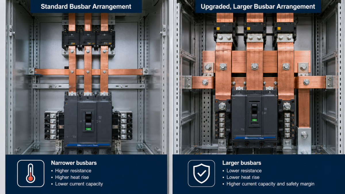 " alt="Engineer conducting a thermal inspection of low-voltage switchgear" title="How Component Choices Impact Panel Thermal Performance." decoding="async" loading="lazy" />
We see heat rise as an outcome of several key variables, not a standalone feature. Each variable presents a trade-off between cost, footprint, and safety. For any given project, we aren't just selling a standard panel like a Moletong GCK or GGD model; we are configuring a system to meet specific operational demands. The final temperature rise is a result of those configuration choices. To make a smart decision, you have to understand what those choices are and how they connect.
Key Variables Driving Heat Rise
The main factors are the continuous current the panel will carry and the fault current it must withstand. A higher continuous load needs larger busbars to keep heat down, which increases material costs. A higher fault rating requires stronger bracing and often different circuit breakers, which impacts both cost and physical size.
Balancing Cost, Performance, and Risk
This is where the decision becomes measurable. As a buyer, you need to see how these factors are balanced. The table below shows a simplified example of how changing one requirement affects the others.
| Variable | Standard Spec (e.g., GGD) | High-Performance Spec (e.g., GCK) | Impact |
|---|---|---|---|
| Continuous Current | 2500A | 4000A | Larger busbars, increased cost, larger footprint. |
| Fault Level (1s) | 50kA | 80kA | Stronger busbar supports, higher-rated breakers, significant cost increase. |
| Internal Arc Need | None | AFLR 50kA 0.3s | Arc-resistant doors, vents, and construction; adds cost and complexity. |
Each choice traces back to a specific need from your project's studies. By reframing the discussion this way, you move from buying a product to engineering a solution.
The Data You Need to Evaluate Heat Rise Without Guesswork
It's hard to know if a panel is truly right for your system. Relying only on a manufacturer's datasheet is a gamble. You need specific project documents to remove the guesswork.
To evaluate heat rise without guessing, you must have the approved single-line diagram, a complete electrical fault and coordination study, and the proposed relay settings. These documents provide the specific load, fault current, and protection timing that determine the real thermal stress on the panel.
 " alt="Engineers reviewing site data and energy storage project documents" title="The Key Documents for Heat Rise Evaluation." decoding="async" loading="lazy" />
We never start a switchgear configuration without these three documents in hand. They form the engineering basis for every component choice we make. A catalog can tell you what a panel can do, but these studies tell you what your panel must do. Without them, any selection is just a guess. For example, the fault study might reveal that a location needs a panel rated for 65kA, making a standard 50kA model unsuitable and unsafe, regardless of its price. These documents turn an abstract requirement into a concrete set of numbers we can design against.
The single-line diagram (SLD) is the map. It shows how all the equipment is connected, from the utility source down to the final loads. It tells us the voltage levels, transformer sizes, and the intended purpose of each circuit breaker.
The fault study provides the hard numbers for worst-case scenarios. It calculates the maximum short-circuit current that could flow at every point in the system. This number dictates the required short-circuit withstand rating (Icw) of the panel and its circuit breakers. A panel must be able to survive this force without catastrophic failure.
The coordination study and relay settings tell us about time. This is the most overlooked part. The study determines how long a fault will last before a breaker trips. The longer the fault current flows, the more thermal energy (measured as we²t) is released into the busbars and components. A well-coordinated system clears a fault instantly at the closest breaker, minimizing heat and damage.
How the Protection Study Changes the Risk Profile
A high fault rating on a panel seems safe, but it isn't the whole story. If the protection system doesn't act fast enough, even the most robust panel can fail.
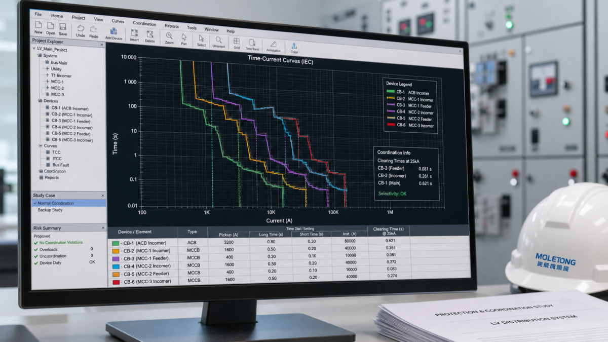
A protection study changes the risk profile by defining the duration of a fault. A lower fault current that is cleared slowly can generate more destructive heat than a higher current cleared instantly. The study ensures breakers are set to trip before the panel's thermal limits are exceeded.
 " alt="Engineer conducting a thermal inspection of low-voltage switchgear" title="Visualizing Risk Reduction with Protection Coordination." decoding="async" loading="lazy" />
A withstand rating cannot be reviewed separately from the protection settings. For example, an upstream time delay can allow damaging thermal energy (I²t) to build at a fault level below the panel's headline short-circuit rating. We therefore review the time-current coordination and let-through energy alongside the mechanical rating.
The real risk isn't just the peak current; it's the total energy let-through. A protection coordination study is designed to minimize this energy. It staggers the trip times of breakers so that the one closest to the fault opens first, isolating the problem immediately. This is called selectivity. When done right, it means the rest of the facility stays online and the fault energy is kept to an absolute minimum. A bad protection scheme can turn a minor fault into a major outage with significant equipment damage. The risk profile is therefore not defined by the panel's strength alone, but by the intelligence of the protection system controlling it.
Final Checks Before Approving a Low-Voltage Panel
You’ve reviewed the studies and approved the design. But how do you confirm the physical product matches the paperwork? Manufacturing errors or component swaps can undo all your careful analysis.
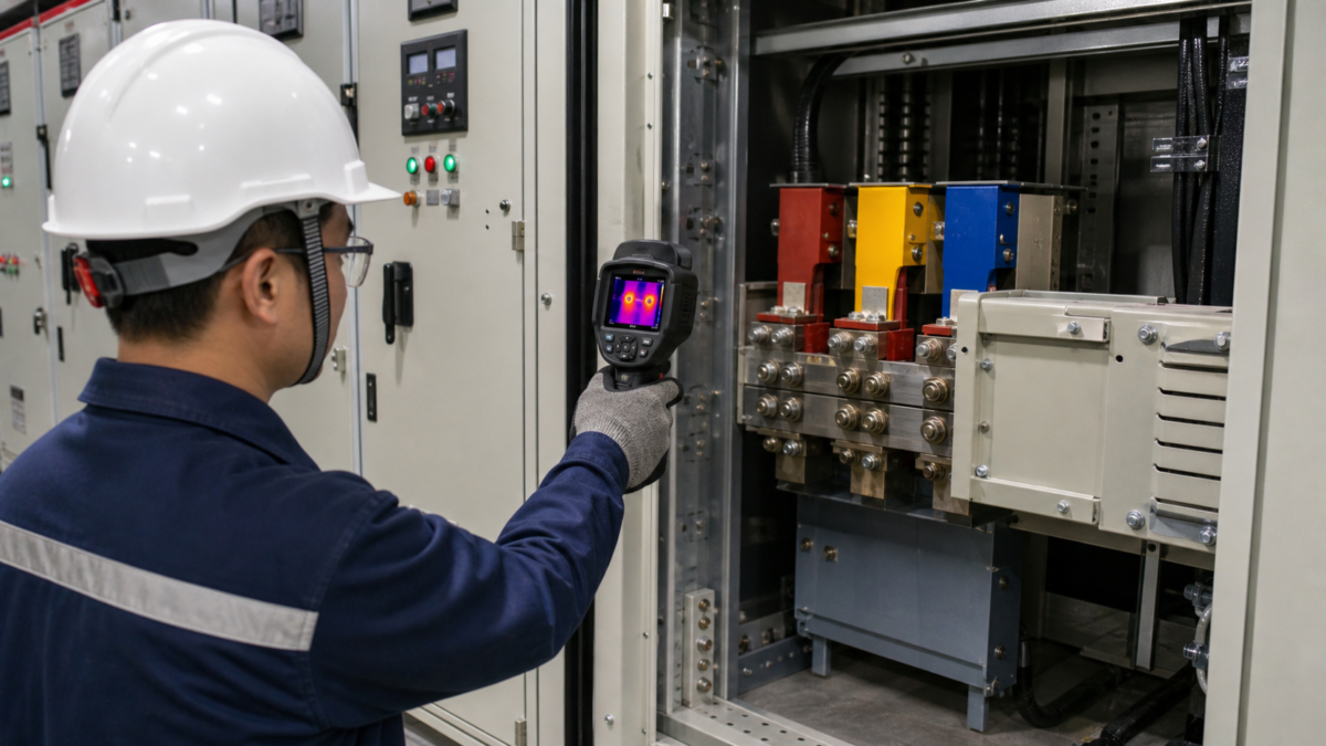
Before final approval, you must physically verify the equipment against the design documents. Use the Factory Acceptance Test (FAT) record and a post-commissioning thermal scan. The FAT confirms correct construction, while the thermal scan proves the panel performs as designed under real operating load.
 " alt="Engineer conducting a thermal inspection of low-voltage switchgear" title="Final Thermal Verification Before Project Handover." decoding="async" loading="lazy" />
Paperwork is one thing, but hardware is another. We always insist on two final checks before signing off on any installation. The first is the Factory Acceptance Test (FAT). This is our chance to see the panel before it ships. We bring the approved drawings and we check everything, point by point. Are the busbars the correct size and material? Are the circuit breakers the exact models specified? Are the internal clearances and supports built as designed? The FAT report becomes a permanent record that the equipment was built correctly. It’s the last chance to catch a mistake when it's still cheap and easy to fix.
The second check happens after the panel is installed and energized. Once the system is running with its normal load, we perform a baseline thermal scan. Using an infrared camera, we inspect all connections, breakers, and busbars for any unexpected hot spots. This scan provides the ultimate proof that the entire system—design, manufacturing, and installation—is working correctly. A clean thermal scan is the best evidence you have that the heat rise is under control. For our Moletong projects involving complex assemblies like box-substations or long bus-duct runs, this scan is a non-negotiable part of our commissioning process.
Conclusion
Verifying heat rise isn't about one number. It is about tracing the panel’s design back to your project’s study values and operating conditions. This approach is how you effectively manage risk.

Leave a Reply