

How Should Buyers Respond to "Relay Coordination Based Placement of Distributed Generation (Dg) Units"?
A vendor claims their DG placement is optimized by advanced relay coordination. This sounds impressive, but how can you be sure their paper promises will hold up in a real-world fault?
Treat relay coordination as a custom design and operating decision, not a catalog comparison. Buyers should demand proof that switchgear selection traces back to project-specific study values and operating scenarios. This makes reliability, safety, and commercial risks visible before you commit to a purchase.
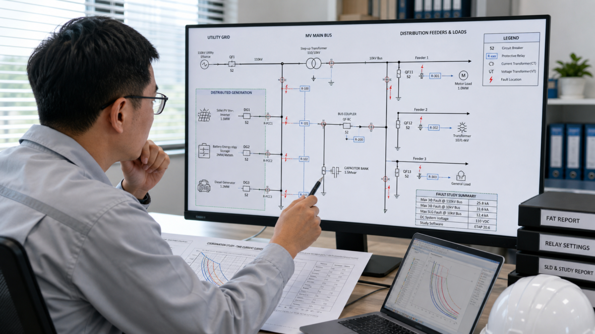
When a supplier presents a solution based on "relay coordination," it’s easy to get lost in the technical details. They might show you impressive-looking software outputs or time-current curves. But my experience has taught me that these are just pieces of a much larger puzzle. The real test isn't what the catalog says; it's how the equipment will behave on your specific site, with your specific loads, and under your specific fault conditions. A slick presentation doesn't guarantee your facility won't experience a costly blackout because of a miscoordinated relay. I’ve learned to push past the sales pitch and focus on the underlying engineering. The rest of this article explains the practical steps I take to do just that, so you can transform this technical topic into a clear business decision.
When Relay Coordination Becomes a Business Case?
Relay coordination often sounds like a technical problem for engineers. But a single failure can trigger widespread outages, damage expensive equipment, and halt your operations, creating a serious financial problem.
Relay coordination becomes a critical business case when it directly impacts system reliability, operational safety, and commercial value. A well-designed scheme prevents minor faults from causing major outages, protecting your assets, personnel, and revenue streams from preventable downtime.
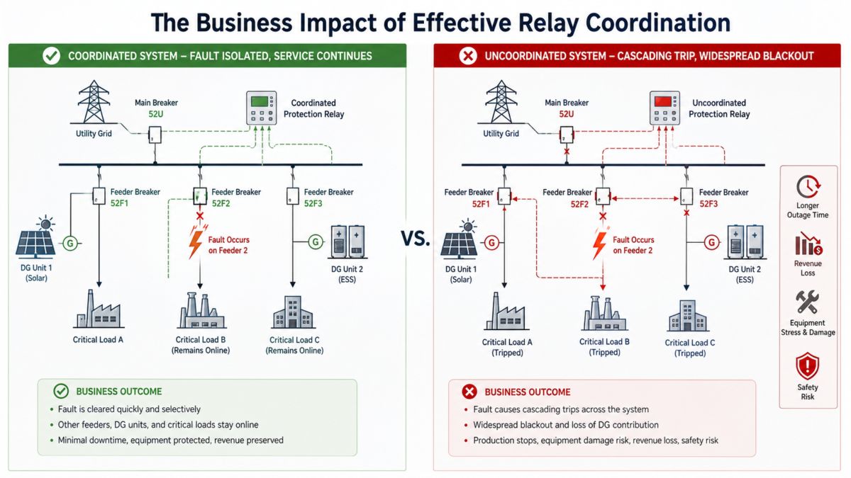
I view protective relaying as an insurance policy for an electrical system. It’s not just about buying a relay with certain features off a shelf. It’s about ensuring the entire system—from the utility connection to your DG units and downstream loads—works together seamlessly when things go wrong. A fault is inevitable; the question is whether your system will isolate it with surgical precision or react with a complete shutdown. The difference between these two outcomes is the business case. Nuisance tripping, where a healthy part of the system goes offline, isn't just an annoyance. It can mean lost production, spoiled inventory, or failure to meet service-level agreements. That's why I insist on shifting the conversation from product features to system performance under specific, stressful conditions. This approach is built on verifiable engineering, not just a manufacturer's standard datasheet.
From Catalog Spec to System Reality
The gap between a product's advertised capability and its real-world performance is where business risk lives. I bridge this gap by demanding study-based evidence.
| Aspect | Catalogue-Based Decision (High Risk) | Study-Based Decision (Low Risk) |
|---|---|---|
| Basis for Choice | Standard features and generic ratings | Project-specific fault levels and load profiles |
| Risk Assessment | Assumes ideal operating conditions | Models downside scenarios and failure modes |
| Performance Guarantee | Implied by product specifications | Verified through coordination study and settings files |
| Outcome | Potential for miscoordination and nuisance trips | Reliable fault isolation and maximized uptime |
Which Relay Coordination Inputs Deserve the Most Scrutiny?
You receive a thick protection study full of data and graphs. But if the inputs are wrong, the conclusions are useless. So, where should you focus your attention to avoid this "garbage in, garbage out" problem?
Scrutinize the assumed available fault current from both the utility source and all DG units. You must also verify the full range of operating scenarios, especially grid-connected, islanded, and parallel-source modes, as these completely change protection requirements.
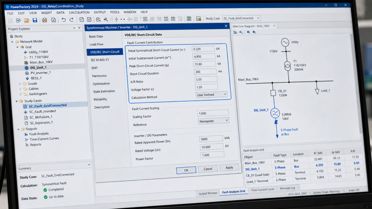
Whenever I review a coordination study, I go straight to the assumptions table before looking at any curves. This is where the foundation of the entire protection scheme is laid out, and it's often where critical errors hide. The single most important input is the available fault current. A vendor might use a generic or outdated value for the utility contribution, but this figure can change over time as the grid evolves. I always ask, "Where did this number come from, and how old is it?" The same scrutiny applies to the DG units. The fault contribution from a solar inverter is vastly different from that of a rotating generator. If the model is wrong, the coordination will fail. I also press hard on operating scenarios. A system designed only for grid-connected operation is a disaster waiting to happen if it ever needs to run in islanded mode. Each scenario requires its own set of protection settings, and I need to see proof that all of them have been analyzed.
How to Stress-Test Relay Coordination Performance?
The coordination study looks perfect under normal fault scenarios. But what happens on a bad day, when a breaker fails to open or the grid unexpectedly disappears? The paper plan needs to survive a reality check.
Stress-test the coordination performance by demanding simulations of downside conditions. These must include breaker failure scenarios, sympathetic tripping analysis, unintentional islanding, and the impact of future system expansion, such as adding more DG units.
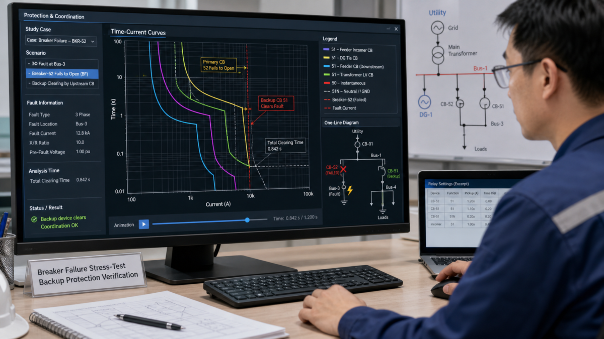
A protection study that only considers ideal conditions is incomplete. I treat it as a first draft. The real test is to see how robust the design is when things don't go as planned. My go-to stress test is the "breaker failure" scenario. I ask the engineer: "If this primary breaker fails to trip, what happens next? Show me that a backup device will clear the fault without causing a catastrophic outage." This simple question reveals a lot about the depth of the engineering. Another key test involves future growth. Many facilities add more solar or storage over time. I need to know if the proposed protection scheme can accommodate that growth or if it will require a complete and costly re-study in two years. By pushing for these "what-if" analyses, I make potential future problems visible today, when they are still cheap and easy to fix. This is about buying a solution for the entire lifecycle of the facility, not just for the day of commissioning.
A Buyer-Focused Relay Coordination Verification Plan?
You're nearing a decision, but you need concrete proof, not just promises. A glossy brochure or a summary PowerPoint is not enough. So, what specific deliverables should you demand to truly verify the relay coordination claims?
A buyer's verification plan must demand a final, approved single-line diagram, the complete fault and coordination study report, the final relay settings files, and the Factory Acceptance Test (FAT) records that prove those settings were properly tested.
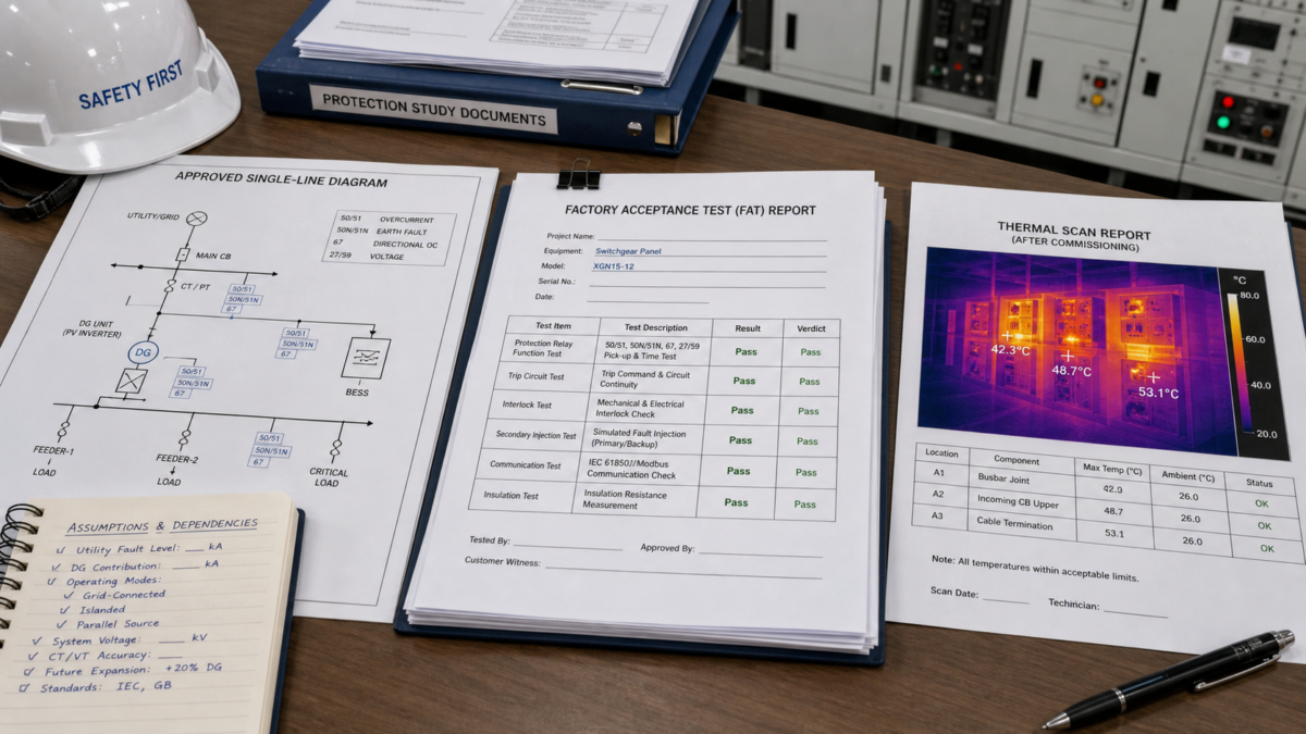
This is the point where I put my full verification plan on the table. It’s a non-negotiable list of documents that I require before I trust any conclusion or use it in a Request for Quotation (RFQ). For me, this is the only way to confirm that the theoretical design has been translated into a real, tested, and reliable system. My list is short but comprehensive. First, the approved single-line diagram is the master plan. Second, the full protection study, not a summary, shows the engineering work. Third, the actual relay settings files are the digital proof of the final configuration. Fourth, the FAT record proves the physical hardware was tested with those exact settings. Finally, I want a thermal scan after commissioning to confirm everything runs as expected under a real load. I also insist on a short assumptions table to make all dependencies clear. When specifying Moletong switchgear like our XGN15-12 or GCK series for a DG project, I expect the client's engineer to provide this package. It ensures the equipment will perform safely in their unique application.
Conclusion
Ultimately, you must treat relay coordination as a site-specific engineering task, not a product feature. Do not trust vendor claims; instead, verify them with a rigorous plan that demands concrete proof.


Leave a Reply