
Which Assumptions Matter Most When Evaluating Hybrid Inverter PV Oversizing?
Are you confused by hybrid inverter PV oversizing ratios? You're not alone. Many attractive proposals become difficult to deliver because they hide critical operating assumptions that can make or break a system.
The most important assumptions are your battery limits, generator behavior, transfer target, and phase arrangement. Off-grid reliability is an operating-sequence problem, not just an equipment-selection problem. Base your decision on these system-level constraints, not a product label.
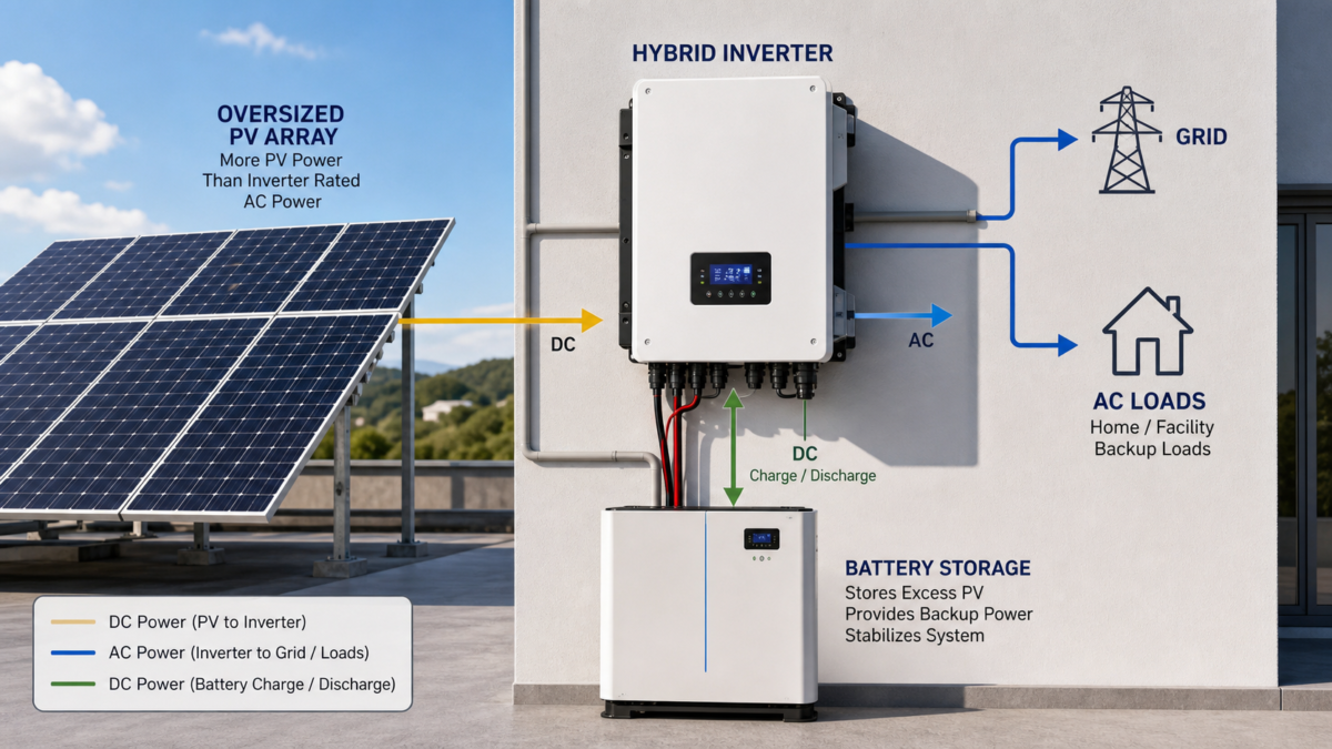
When I advise a buyer on hybrid inverter PV oversizing, I always start with one question: what are we assuming about how this system will actually run? The answer reveals whether a design is robust or just a sales pitch. The practical issue is that a reliable off-grid system depends on how all the parts work together in sequence. This is far more important than a simple oversizing ratio on a datasheet. I would build a decision model around the system’s real-world limits and test it against the most inconvenient operating conditions. Let's explore how to do that.
Start with the Hybrid Inverter PV Oversizing Customer Problem, Not the Product?
Your system fails during a critical moment, even though the inverter datasheet looked perfect. The real problem isn't the equipment, but the sequence of operations that nobody tested beforehand.
True reliability comes from solving the customer's operating-sequence problem. This means understanding how the system behaves during grid loss, generator startup, or when the battery is full. A product label can't tell you this, but a clear operating model can.
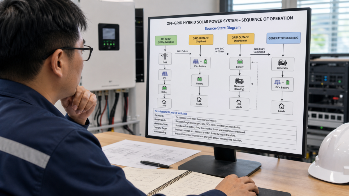
I've seen many projects where a fantastic inverter was chosen, but the system still failed. The root cause was a mismatch between the design assumptions and real-world conditions. For example, the designer assumed the generator would start instantly, but it had a 30-second warm-up. That gap was long enough to cause a total system collapse. We need to stop focusing on the product's peak power and start defining the operating states. I find it helps to map out the system’s behavior in a simple table. This turns a complex problem into a clear discussion with the supplier.
Key Operating Modes and Assumptions
To make this practical, I always create a table that outlines the different source states and what needs to happen for the system to remain stable. This becomes a checklist for validating any proposed design.
| Operating Mode | Primary Source | Secondary Source | Key Assumption to Test |
|---|---|---|---|
| Normal On-Grid | Grid | PV + Battery | Does the system correctly limit export power if required? |
| Grid Outage (Day) | PV + Battery | Generator (Standby) | Can the inverter handle load surges without the grid’s support? |
| Grid Outage (Night) | Battery | Generator (Standby) | What is the minimum battery state-of-charge to trigger the generator? |
| Generator Running | Generator | PV + Battery | Will the inverter try to back-feed the generator? How is this prevented? |
This simple exercise forces everyone to think about the sequence of events. It moves the conversation from "Which inverter is best?" to "How will this system behave when X happens?" That's a much more productive starting point.
How Battery Limits Shapes the Hybrid Inverter PV Oversizing Design?
You've installed a huge PV array to maximize energy harvest. But on sunny days, the system constantly shuts down your PV production, wasting free energy and extending your payback period.
The battery's ability to accept a charge is often the real bottleneck, not the inverter. If your PV array produces more power than the battery can absorb, the inverter has no choice but to curtail PV output. The design must match PV generation to the battery's charge limits.
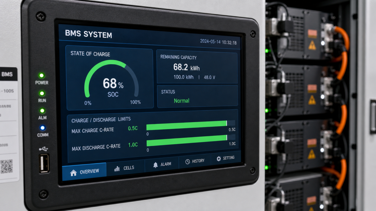
I remember a project for a remote lodge that was designed with a 2:1 PV-to-inverter ratio. It looked great on paper. The problem was that the battery bank was undersized for the massive PV array. By 11 AM on a sunny day, the battery was full. The inverter then had to drastically cut PV production because there was nowhere for the energy to go. The customer was frustrated because they paid for a large PV array but were throwing away most of its potential output.
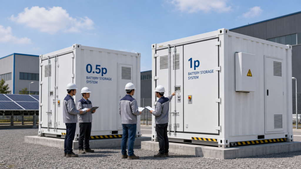
The key specification here is the battery's charge C-rate, which defines the maximum current it can safely accept. For example, a 100 kWh battery with a 0.5C charge limit can only absorb 50 kW of power. If your "oversized" 80 kW PV array is producing at full tilt, the inverter must throw away 30 kW of power once the local loads are met. The design process must start with the battery's continuous charge and discharge capabilities and its usable state-of-charge (SoC) window. These parameters, not the inverter's nameplate rating, define the true dynamic capacity of your energy system. An effective design ensures the PV output curve fits within the battery's acceptance profile.
When Neutral/earth Scheme Changes the Economics?
Your installer tells you the approved inverter requires an expensive isolation transformer. This unexpected cost blows your project budget and timeline, all because of a detail hidden in the wiring schematics.
The neutral-to-earth bonding scheme can fundamentally change your project's cost and complexity. Some inverters create a floating neutral in off-grid mode, which may not be compatible with your site's existing electrical system or safety standards, forcing costly modifications.
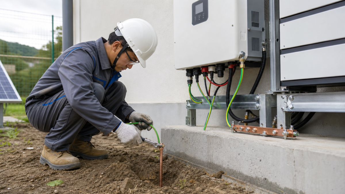
This is one of the most overlooked "gotchas" in off-grid and hybrid design. In many standard electrical systems (like a TN-S scheme), the neutral and earth conductors are bonded together at one point, usually at the main switchboard. When the grid fails, some hybrid inverters disconnect the grid neutral, creating a new, separate electrical system for the backup loads. The question is, does the inverter create a new neutral-to-earth bond internally?
If it doesn't, you now have a "floating" system, which can cause problems for safety switches (RCDs/GFCIs) and some appliances. If it does create a new bond, you have to ensure there is never a situation where the grid and inverter bonds are connected at the same time, as this can create dangerous ground loops. In one case, a client had to install a separate 50 kVA isolation transformer simply to satisfy this requirement for their chosen inverter. It added nearly 15% to the total project cost. A different inverter choice, one designed to work with the site’s existing earthing, would have avoided this completely. This is why you must confirm the inverter's off-grid earthing behavior before you approve the design.
Turning Hybrid Inverter PV Oversizing into Clear Specifications?
You've approved a design, but you feel uncertain. You don't have a clear way to verify that the installed system will perform as promised during a real-world disturbance or power outage.
Transform assumptions into a list of specific, testable performance requirements. Instead of accepting a generic proposal, demand evidence like a source-state diagram, a disturbance log, and a witnessed black-start test. This makes the supplier prove the system's reliability.
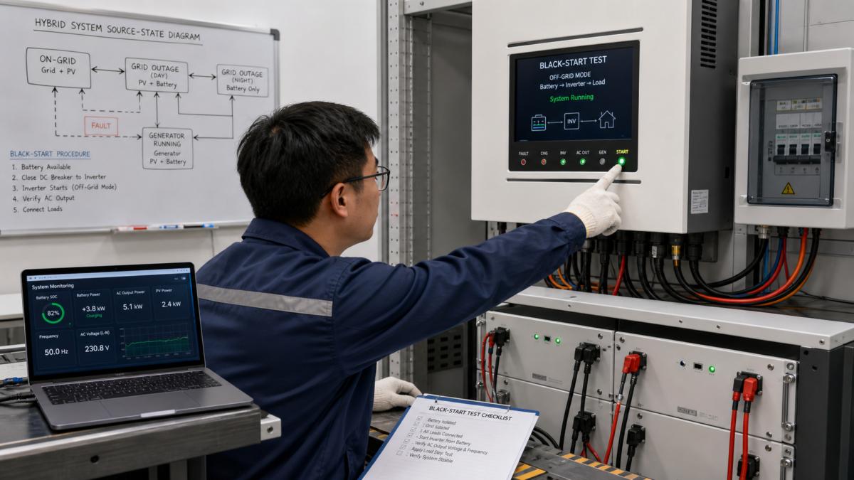
A good proposal shouldn't just be a list of equipment. It should be an operating manual. At Moletong, I would insist on mapping our single- and three-phase hybrid inverters only to verified model limits confirmed by testing. This means turning principles into a clear specification sheet. For any complex hybrid project, I ask the designer to provide a simple source-state diagram. This is just a flowchart showing how the system moves between states like "On-Grid," "Off-Grid," and "Generator Running." It clarifies the logic.
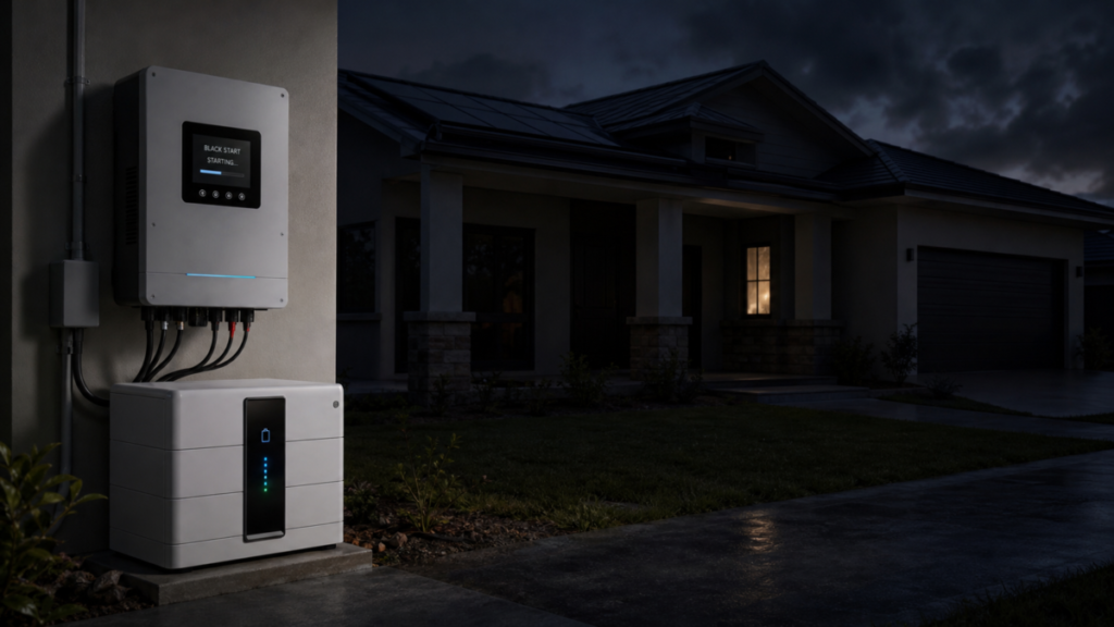
Next, I ask for a simulated disturbance log. What happens if the grid fails while the PV is at maximum output and a large motor starts? The log should show the voltage, frequency, and battery current second by second. Finally, the most important test is the black-start. This means starting the system from a completely dead state using only the battery and inverter. It is the ultimate test of system stability. Before you approve a final design, you should ask the supplier these exact questions:
- Can you provide a source-state diagram showing all operating modes?
- How does the system handle a 100% load step in off-grid mode?
- What is the documented procedure for a full black-start?
- Can you confirm the inverter's neutral-to-earth bonding behavior in both on-grid and off-grid modes?
- How is PV generation curtailed when the battery is full and loads are low?
These questions force your supplier to demonstrate reliability, not just sell you a product.
Conclusion
A successful hybrid inverter design depends on testing the right operational assumptions. Focus on battery limits, operating sequences, and clear, testable specifications to ensure your system is reliable in the real world.
Leave a Reply