

Battery Communication Error: A Practical Design and Procurement Guide?
You chose a battery and inverter that were supposed to be compatible. But now you're facing constant communication errors, system shutdowns, and a project that is going nowhere fast.
A buyer should treat battery communication compatibility as a specific, verifiable design choice. This requires more than just matching voltage or chemistry. It demands documented proof of interoperability, such as a versioned compatibility matrix, commissioning logs, and specific evidence of protocol-level communication between the exact models.
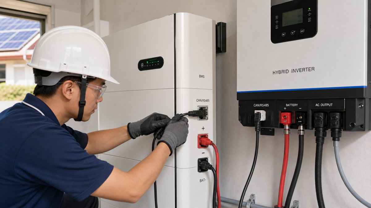
I've learned this lesson the hard way over the years. A simple checkmark on a datasheet is not a guarantee of performance. The risk of getting it wrong is too high, affecting everything from system uptime to the fundamental safety of the installation. That's why I now approach battery communication not as a given, but as a critical system parameter that must be designed, specified, and verified with an almost paranoid level of detail. In this guide, I will walk you through the exact process I use to de-risk this crucial interface and ensure a project's success. This is about moving from hope to proof.
When Battery Communication Error Becomes a Business Case?
A simple communication error often seems like a minor technical glitch. But this glitch can halt operations, trigger safety shutdowns, and create huge financial losses. This is not just an IT problem.
A communication error becomes a business case when it directly impacts system reliability, operational safety, or commercial value. It can void warranties, reduce performance, or create unsafe conditions, turning a technical detail into a significant financial and operational liability.
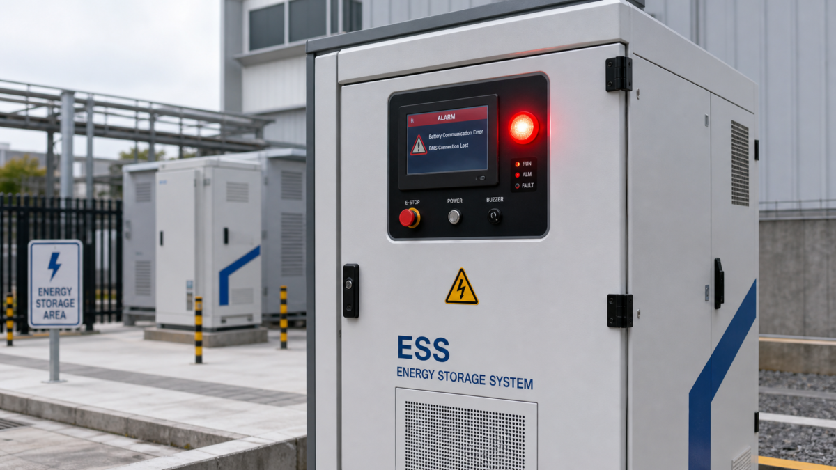
I remember a project where an intermittent communication fault was initially dismissed. The system would trip offline for a few minutes each day. The real problem was that these trips coincided with peak production hours, costing the facility thousands in lost revenue. The "minor glitch" was actually a major business disruption. The inverter couldn't get accurate state-of-charge updates from the battery management system (BMS), so it would default to a safe, non-operational state. This highlights how a breakdown in data flow can cripple the physical operation of a multi-million dollar asset. It's essential to map these technical symptoms to their real-world business consequences.
From Technical Glitch to Financial Risk
To make this clear for stakeholders, I often use a simple table to show how a small error escalates into a big problem. This helps everyone understand that fixing communication isn't just a task for the engineers; it's a priority for the entire business.
| Impact Area | Technical Symptom | Business Consequence |
|---|---|---|
| Reliability | Inverter loses BMS connection, system shuts down. | Unexpected downtime, lost production, failure to meet peak shaving targets. |
| Safety | BMS cannot send cell over-temperature warnings to the inverter. | Inverter continues charging, leading to thermal runaway and potential fire. |
| Commercial Value | Incompatible components are used, violating manufacturer terms. | Warranty is voided, leading to unbudgeted replacement costs for failed equipment. |
Which Battery Communication Error Inputs Deserve the Most Scrutiny?
The datasheets both said "compatible," but your system keeps failing. You checked the voltage and chemistry, so what else could be wrong? The problem is in the details you're not looking at.
Scrutinize specific model numbers, firmware versions, and communication protocols like CAN or RS485. A simple brand match is not enough. A versioned compatibility matrix is essential, as even minor firmware updates from a manufacturer can completely break communication.
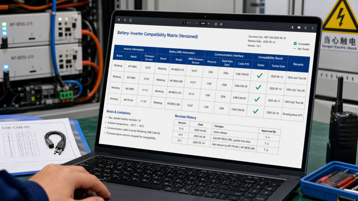
In my view, a chemistry or voltage match proves almost nothing about communications or warranty compatibility. It's the bare minimum, like checking if two people speak the same language without knowing if they understand the same dialect or vocabulary. The real compatibility is found at a much deeper level. I've seen systems with dozens of batteries where the master/slave communication logic failed because the inverter's protocol couldn't handle that specific battery count, even though it worked perfectly with a smaller number of the same model. The manufacturer's compatibility list didn't mention this limitation. That's why I insist on knowing the exact rules and limitations before I even consider a product pairing. We must look beyond the marketing claims and dig into the technical nitty-gritty.
Beyond the Datasheet
I always push for documentation that covers these four critical areas:
- Exact Model Numbers: Not just the series, but the full model number for both the battery and the inverter.
- Firmware Versions: Both the BMS and the inverter firmware must be specified. A change in one can break the entire link.
- Physical Layer and Protocol: Is it CAN or RS485? What are the baud rate, termination requirements, and pinouts? The physical connection must be perfect.
- Application Logic: This covers master/slave rules, the maximum number of batteries supported, and how the system handles the addition or removal of a battery module.
How to Stress-Test Battery Communication Error Performance?
Your system works fine during a simple commissioning test in the workshop. But what happens during a grid outage, a rapid charge, or a deep discharge? A simple "on" test isn't enough.
Stress-test communication by simulating real-world operational extremes. Force rapid charge and discharge cycles, simulate a grid failure to test the backup response, and briefly overload the system. You must observe how the BMS and inverter communicate under pressure.
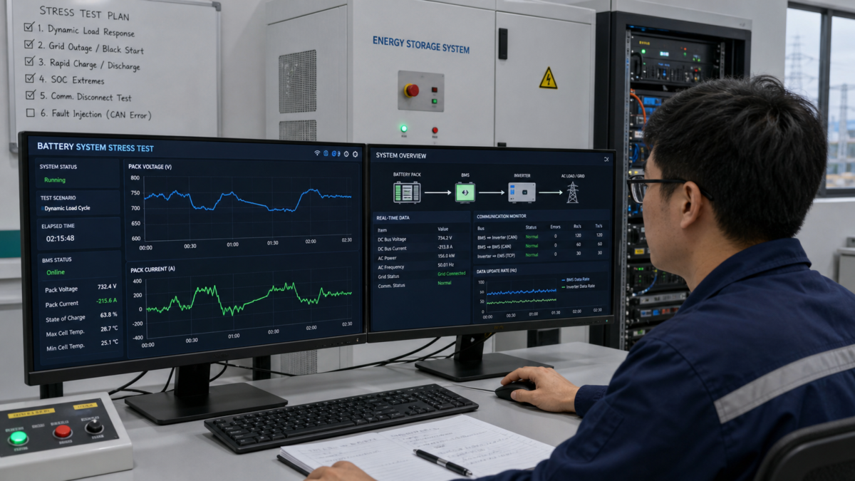
The goal of a stress test is to make the downside visible before it happens in the field. I want to see how the system behaves when it's pushed to its limits. One of my go-to tests is to physically disconnect the communication cable while the system is operating under a heavy load. What happens next tells you everything. Does the system fail gracefully and safely, shutting down in a controlled manner? Or does it behave erratically, potentially creating a dangerous condition? A robust system will have a clear, predictable, and safe failure mode. Another critical test is a "black start," where you simulate a total power loss and see how the battery and inverter re-establish communication and restart the system on their own. If they can't do this reliably, the system isn't fit for any critical backup power application.
Simulating Real-World Failure
A good stress test plan should try to break the communication link in realistic ways.
- Dynamic Load Response: Apply a sudden, large load. Watch the data stream to ensure the inverter receives updated power limits from the BMS in real-time. A delay could cause the inverter to over-discharge the battery.
- State-of-Charge (SOC) Extremes: Push the battery to its maximum and minimum SOC limits. Verify that the inverter respects the "charge disable" and "discharge disable" commands from the BMS.
- Fault Injection: Introduce fake error messages into the communication bus if possible. See if the system correctly identifies the fault and takes the appropriate protective action.
A Buyer-Focused Battery Communication Error Verification Plan?
You need to write a Request for Quotation (RFQ) for a battery system. How do you ensure you get a system that works, not just a collection of incompatible parts that look good on paper?
A buyer's verification plan must demand documented proof. Ask for a dated and versioned compatibility statement for the exact battery, inverter, firmware, and cable. This document must be supported by connector photos, packet/register evidence, and a detailed commissioning log.
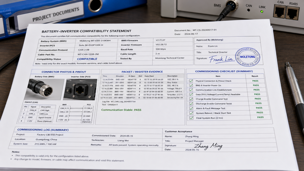
This is the standard I hold my suppliers to, and it's the level of detail I would want to see from Moletong or any other manufacturer. I would only publish a dated Moletong compatibility statement for an exact combination of products. The statement would be invalid if any part of that combination changed—the battery model, the inverter firmware, or even the communication cable part number. This sounds strict, but it's the only way to create accountability and prevent the "it should have worked" conversations after a failure. Before trusting any compatibility conclusion or using it in an RFQ, the supplier must provide a complete evidence package. This shifts the burden of proof from the buyer to the seller, which is exactly where it belongs.
The Ultimate Compatibility Checklist
I would not proceed with a purchase until the supplier provided the following five items for my specific project configuration:
- Versioned Compatibility Matrix: An official document that lists my exact inverter model number and firmware version alongside the exact battery BMS model number and firmware version, with a clear "compatible" status.
- Connector Photo and Pinout Diagram: A clear, high-resolution photo of the physical communication cable connectors on both the battery and inverter, with a diagram confirming the pin-to-pin wiring.
- Packet/Register Evidence: A log file or screenshot showing a successful exchange of data packets between the two devices. This proves they are not just physically connected but are actually sharing and understanding data like SOC and voltage.
- Commissioning Log: A signed-off report from a previous, identical installation, detailing the steps taken to establish communication and the final, stable operating parameters.
- Assumptions Table: A short table stating any limitations, such as the maximum number of batteries, required ambient temperature range, or other conditions under which the compatibility is guaranteed.
Conclusion
Treat battery communication as a critical design decision. Demand specific, versioned proof of compatibility to protect your investment, ensure safety, and guarantee performance. This is the only way forward.



Leave a Reply